From the navigation bar on www.metomics.com, select ‘M:STDIO’
Getting Started
If you’re a first-time user of M:STDIO you’ll be looking for a few hints and tips on how to get the most out of our 3D modelling tool. We’ve been working with the lovely people at Mecabricks to create a bespoke platform just for METOMICS and are really excited about taking our Metal Designer Blocks digital!
If you’ve used Mecabricks before, you’ll be familiar with the controls in M:STDIO, however if you’re more used to LDD or MLCAD you may need to read-on.
This ‘quick-start’ guide is intended to get you up and running as quickly as possible and includes guidance on its basic functions. M:STDIO is a versatile modelling tool and we want you to get the most out of it, so we’ll be releasing further tips soon.
M:STDIO can be trialled without the need to create an account, however, to access certain functions, a Metomics account will be required.
In this simple 10-Step guide we’ll show you how to add and move parts, orientate and align, rotate and colour blocks. Each step assumes the previous step has been undertaken.
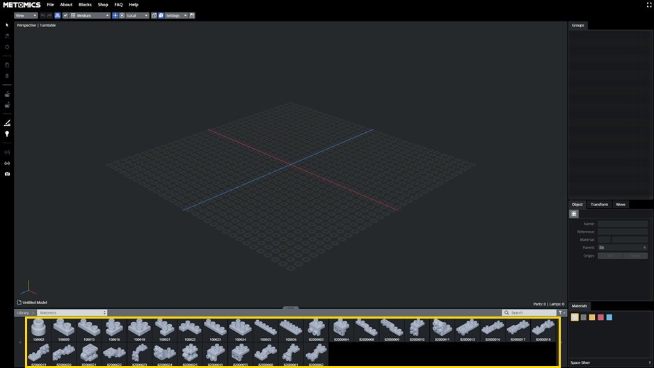
The lower part of your screen is where you select the block that you want to add to your build area. Extend the tab to reveal all available blocks. Select the block you want by clicking on it. You may see a “progress” indicator displayed while the block loads.
Tip: if a block is selected when you choose a colour, the colour of the selected block will change.
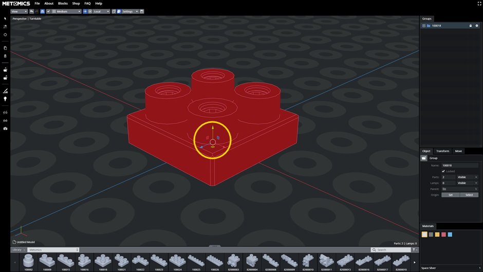
The first block will be placed at the origin (X, Y and Z co-ordinate of 0, 0, 0). Notice the three differently coloured arrows near the block. Each block will have one of these and it will be displayed when the block is selected. The red arrow points along the block’s X axis, the green arrow points along the block’s Y axis and the blue arrow points along the block’s Z axis. You will see the impact rotating a block has on these arrows in step 10. It is also worth noting that in the bottom left hand corner is a similar (but smaller) red, green and blue axis indicator. These are used to indicate the current orientation of the view of the model being built. When you rotate the view, this indicator will rotate correspondingly.
Tip: the currently selected block is shown in red.
In M:STDIO a block is moved by moving the cursor onto the axis for the direction which you want to move the block. The arrow of the selected axis will change colour to yellow (fig. 5 shows that the Z axis has been selected). Click and hold the left mouse button down and drag the block in the direction which you want it to move.
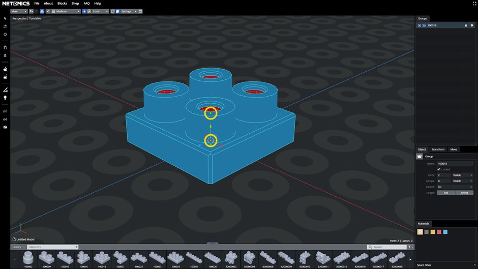
Tip: when you move the mouse over the selected brick, it will turn blue.
When you select a block, orange points are displayed. One use for these points is to determine where the next part will be added. When you position the cursor over a point, the point will turn green (in fig. 6 the upper point has been selected). Clicking the left mouse button will “lock in” the point as the target point.
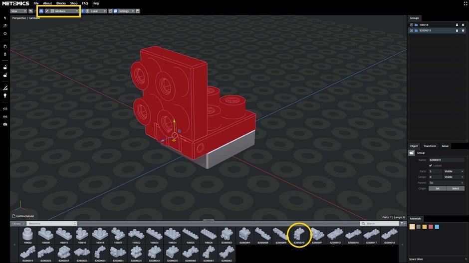
Pick the next block to be added by selecting it from the list at the bottom of the screen (repeat step 3). The block will be added to the model using the target point of the currently selected block. If a point on the model is not selected when the new part is picked, the new part will be added at the model’s origin (0, 0, 0).
Tip: to accurately position each block within the build area, the Transform Grids tab can be used (see step 8).
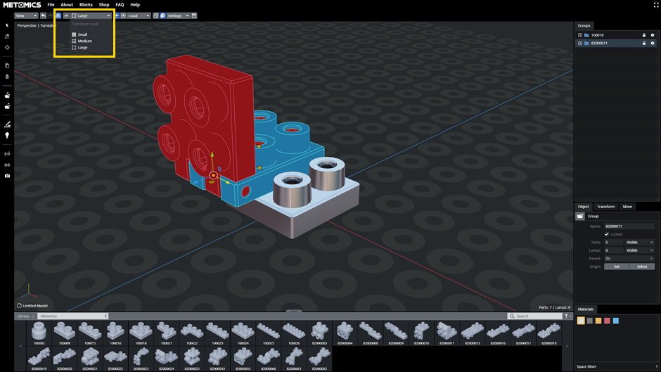
The Transform Grids tab can be used to more accurately position blocks after they have been added to the build area. Click on the drop down menu to reveal three settings; small, medium, large. Depending on which block you are moving, you will need to select the relevant setting.
Tip: for reference, the medium setting will move a block equal to the thickness of a single block (useful for stacking blocks), the large setting will move a block equal to the centres of the block posts (useful for lateral positioning) and the small setting will provide ‘micro adjustment’ as required.
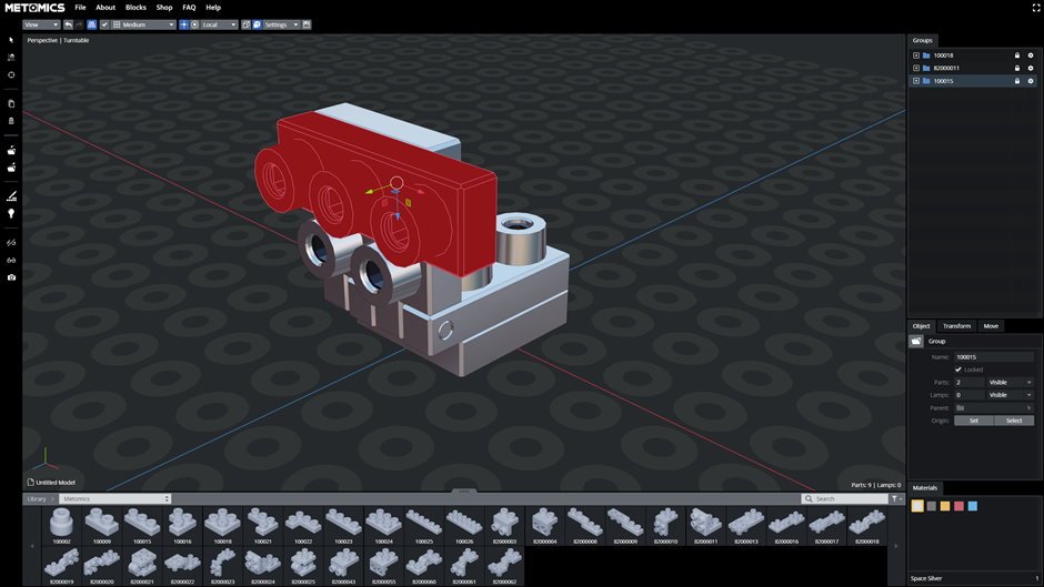
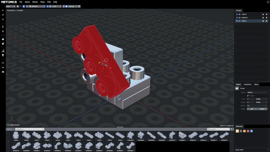
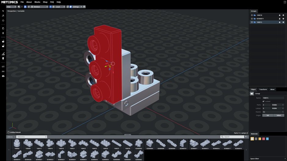
Having placed a block, the arrow keys on your keyboard can be used to quickly rotate the it by 45 degrees along different axes. Pressing the right arrow key once will rotate the block clockwise around the Y axis (see figure 10a) assuming the viewpoint for the rotation is looking towards the block’s axes origin.
Pressing the right arrow key a second time will rotate the block clockwise another 45 degrees around the Y axis.
The key combinations to rotate a block around an axis are;
Left arrow – Anti-clockwise rotation around the Y axis
Right arrow – Clockwise rotation around the Y axis
Up arrow – Anti-clockwise rotation around the X axis
Right arrow – Clockwise rotation around the X axis
Shortcut
A – Select all / Deselect all
B – Start box select tool. Elements in the box will be added to the selection. Press shift to remove them
C – Screenshot
D – Clone selection
H – Hide selection
ALT + H – Show everything
I – Invert selection
J – Group selection
Alt + J – Ungroup selection
L – Display Lamps
M – Toggle between translation and rotation gizmo
P – Select Pivot Point
Q – Toggle between small, medium and large transformation grid
R + (X or Y or Z) + numerical value – Rotation along selected axis in the global or local space
S – Select snap point
CTRL + S – Save
T + (X or Y or Z) + numerical value – Translation along selected axis in the global or local space
V – Toggle between Global and Local Space
W – Display selection tools
Z – Toggle between shaded, shaded with edges and wireframe mode
CTRL + Z – Undo
CTRL + Y – Redo
CTRL + Left Click – Add or remove element to or from the selection
NUMPAD ‘8’ or ‘2’ – Translate along Z axis
NUMPAD ‘4’ or ‘6’ – Translate along X axis
Page Up or Page Down – Translate along Y axis
← or → – Rotate selection 45° along Y axis
↑ or ↓ – Rotate selection 45° along X axis
Home or End – Rotate selection 45° along Z axis (keys next to page up and page down keys on an apple keyboard)
Esc – Deactivate selected tool / Cancel rotation or translation
Ctrl + Click – Add or remove a part/group to the selection
Numpad ‘5’ – Toggle between Perspective and Orthographic projection
Numpad ‘9’ – Toggle between Turntable and Trackball orbit style
Numpad ‘0’ – Reset the position of the camera
Ctrl + Numpad ‘3’ – Left view
Numpad ‘3’ – Right view
Ctrl + Numpad ‘1’ – Back view
Numpad ‘1’ – Front view
Ctrl + Numpad ‘7’ – Bottom view
Numpad ‘7’ – Top view
Numpad ‘.’ – Centre selection or scene
Space – Change camera orientation
Del or Back – Delete selection


